|
|
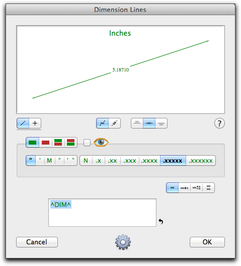
In the tool's dialog, choose whether the tool will be constrained (cross) or unconstrained (diagonal line) to snap angles. This dialog and all of the dimensioning tools in WildTools now use colors for dimensional units. Just remember "Wine and Greenbacks". Metric is wine color in deference to French wine. Green is for U.S. greenback dollars. The dimension styles of single and dual dimensioning should be immediately obvious. The eye button is the 'show unit' control. The effect of clicking on this button is to show/hide dimension units and will be immediately obvious in the sample window. Tolerance choices are handled as four dimension styles. As you click on these choices, the text editing boxes for the dimension and tolerances change. In the case of limit tolerances, you can only edit the tolerances. You may type in the dimension text editing box. This allows you to place a prefix or suffix in the dimension text. The dimension values will be placed between the up-carets (^). If the up-carets are removed, no dimensional value will be placed in the drawing and the text for the dimension will be exactly what you typed. A carriage return can be placed in the dimension text by pressing the Return key. (Because of this, you may use the Enter key alone as a shortcut for clicking on the OK button in the dialog.) A reset button is provided to reset the dimension text. This is provided in case you forget the '^DIM^' syntax. The reset button uses the default suffix for the Radius (R) and Diameter (Ø) dimensioning tools, which share this dialog box with all other dimension line tools. Below the example window, you can change the choice for whether the dimension text is to be rotated. Click on the button repeatedly to toggle between the two choices. If the dimension text is rotated, you can select from three dimension text positions (above, centered, or below). If not, the dimension text position must be centered. The last choice with the dimension text position buttons is for dual dimensioning. Dual dimensioning works by the simple device of placing two separate dimension line objects in the drawing, one for the English 'side of the ruler' and one for the metric side. Below the example window, you can change the choice of whether English or metric is the controlling (top) dimension for dual dimensions. Click on the button repeatedly to toggle between the two choices. Note: You do not have an arrows-inside/outside choice for the dimension line tools. All arrows are automatically inside, however if the dimension is short, the arrows are flipped outside in accordance with the settings in the PowerCADD Dimensions Preferences dialog, however this will not happen if you use a slash-type arrow. To draw a dimension line, click and drag in the drawing with the normal, line-drawing action.
The Dimension tools in WildTools 'share' the same dimension text attributes (Font, font size, etc) as the PowerCADD dimension line tools. Thus, to set the dimension text attributes, select any of the WildTools dimensioning tools and use the Attributes menu or Defaults Window to set the text attributes of the tool. Converting Lines to Dimension Lines
This tool 'shares' (luv that California-word!) the same dialog as the Dimension Line tool. Please see the Dimension Line tool above for a full description of the dialog.
To draw a dimension line, place the cursor in the drawing area at a location that will represent the starting point of the dimension. Press the mouse button. Drag away from the starting point. As you move the mouse, a line will follow the mouse. This line represents the two points being dimensioned. You may tab into the Edit Window to edit the length and angle of the line. Release the mouse button to complete the line. Move the cursor away from this line to locate the dimension line with the witness lines. As you move the mouse, you will see the witness lines being formed. You may press the Shift key to constrain the dimension line to be parallel to the two points being dimensioned. Click the mouse to complete the operation. The dimension line and witness lines will be placed in the drawing.
As any fool knows, stack dimension tools in CAD programs are worthless because they assume you know in advance all of the points that you want to dimension, and also that you will begin all of the stack dimensions at the same point. That's ludicrous, of course, but all CAD programs have them because magazines publish charts of required features. Yep, we've got a stack dimension tool, but the best thing you can do is turn it off and learn how to use the Stack Guideline tool effectively. But, hey, it's a free country and if you want to use this silly thing, be our guest!
To use the tool, use it just like the Leader Dimension Tool. Note that if you tab into the Edit Window, the new dimension line starting point changes, not the end point. This is because the tool is normally used to place typed dimensions that are much longer than the actual drawing.
|
![]()
Go back to WildTools