Transponder Antenna Problems
![]()
Transponder Antenna Problems |
|
|
This article appeared in the March 1992 Falco Builders Letter. |
I've been hearing reports that a few of our Falcos have experienced marginal performance from their transponder antennas. Steve Wilkinson's Falco occasionally gets lost from Center depending on which way the plane is flying. Charles Gutzman reports much the same thing, and he moved the antenna to the landing gear access panel just outboard of wing station 2. Then in January, I got a letter from Bjoern Eriksen in Norway, which said:
"I have noticed that several builders have had problems with the transponder. So have I and the setup was as follows: All antennas were tested for shorts and standing waves (with the appropriate frequencies) before covering of the aircraft. All radios (brand new) were bench-tested before installation. When installed in the aircraft and connected to its antenna, the transponder appeared to drift off the correct frequency (2-4 MHz). The aircraft was flown with very short range on the transponder (2-3 nm). All other radios (all King) including the DME were operating normally.
"The first step was to bench-test the transponder again. It worked perfectly normally. Secondly, we tried to interchange the antenna with the DME. This gave no improvement, but we noticed that the transponder now drifted to the other side of the frequency band. This indicated that we probably had a problem with the length of the antenna cables. We made a cable that brought the transponder frequency just in the middle, and we test flew the aircraft. Negative results.
"By this time, more or less the entire Widerøe airline's radio staff was engaged in the problem, and the prestige was quite high. I will not tire you with all the solutions we tried, but finally we decided to put on a standard King transponder antenna. From that moment, everything has been working perfectly. The sensitiveness to the antenna cable length was also gone.
"Obviously, the King transponder wants a King antenna. Please don't ask me why this is not the case with the DME which works perfectly with the 'Falco' antenna. The transponder antenna is mounted externally on the inspection cover of the autopilot servo. This location gives a very light 'noise' from the transponder (when transmitting) into the audio system. Turning the David Clark intercom box 90° solves most of the problem. When I get time, I will try a different location for the antenna."-Bjoern Eriksen
Antennas are a complete mystery to me, and I sent a copy of this letter to Jim Weir, who designed the antenna. Jim said he didn't understand the problem. Our transponder antenna is the same as the antenna he designed for the Bellanca Viking, which passed a number of FAA certification tests, and it's been a popular antenna design used in many other wood and fiberglass airplanes. Jim is swamped with work, and he apologized for not having the time, but said something incomprehensible about running a gobbledegook test at fiddermajiddit frequencies and to get back with him.
I don't understand any of this stuff, but I remembered that at the Great Oyster Fly-In, Falco builder Michael Scaturo had brought along a bunch of computer analysis charts that he had done on our nav splitter. Michael is a microwave engineer at Hoechst Celanese, and he works on designing little gadgets that hook up on each end of a fiber-optic cable. It's some kind of a rectifying multiplexer gizmo that allows you to send lots more signals through a fiber. It makes the light waves happy, and these little babies catch a good wave as a result. It's good, and people pay money for these things.
Conversations like that give you a little taste of what it would be to have Alzheimer's when people start discussing complicated things, like toilet paper. So when Jim Weir mentioned this test, I thought of Michael Scaturo. Michael said he'd be happy to run some tests, and he quickly reported back that he had found the problem and had come up with a solution. So without further ado, I'll just turn this keyboard over to Michael to explain it all.
Michael Scaturo's Notes
When Alfred told me about the antenna problem and asked if I could help,
I happily agreed-how often do work and play overlap so well. Now I could
use all those neat expensive toys in my lab to make the Falco a better plane...
to make my Falco a better plane.
I put the transponder/DME antenna in my kit together (the hole in the ground plane was 5/16" and had to be enlarged to 3/8" for the insulating washers to fit properly) exactly as in the plans and put it on the HP 8510 Network Analyzer for a look-see. The results are shown in Figures 1 & 2. I'll try to explain these in simpler terms in a minute, but first bear with me on the technical stuff. Figure 1 is a plot of SWR (Standing Wave Ratio) on the Y-axis versus frequency on the X-axis. Figure 2 is a Smith Chart showing the exact impedance of the antenna over the frequencies of interest. The frequencies we're interested are in between the triangles numbered 1 and 2, known as markers. Marker 1 is at about 1000 MHz and marker 2 is about 1100 MHz-transponders broadcast at 1090 MHz.
The Standing Wave Ratio is a measure of how much power goes out of the antenna and how much is 'reflected' back towards the transmitter. At these frequencies, radio waves start to behave a little like light, and they can bounce off things-this is how radar works. These reflected waves interfere with the waves going to the antenna and set up a wave pattern that stands still on the cable feeding it, hence the term Standing Wave. The "Ratio" part is just a measure of how big these waves are. SWR is expressed as a ratio with 1.0:1 being perfect-there's no reflection and everything goes out the antenna. 2.0:1 means that about 33% of the power is reflected back, 3.0:1 means about 50% of the power is reflected back, and so on.
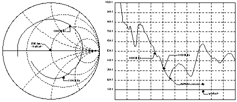
Figure 2 Figure
1
On the SWR plot (Figures 1 and 3), 'perfect' is the second line up from the bottom. This is 1.0:1, the second line up is 2.0: 1, the third 3.0:1, etc. The squiggley line, which is our antenna, can never go below the second line, but the closer it gets to this line the better it is. We can see from Figure 1 that in the best case, at 1100 MHz, the SWR is about 3.25:1. This means that only about 47% of the power is going out of the antenna, the rest is reflected back to the transponder. Down at 1000 MHz, only about 35% of the power is going out of the antenna. We can also see that the resonance dip is not very well defined, and it is shifted to the right. This is an indication that the electrical connection is not too good and that the center element is a little too short.
To the transponder, the antenna looks a little like one of those two-way mirrors at the police station where you can see the suspects but they can't see you. This is because some light goes through to your eyes but the rest is reflected back at them. We want to try to make the antenna look as if it's a clear plate of glass so we can see ATC and they can see us-except in the case of busting the TCA, but that's another story....
The Smith Chart shows the impedance of the antenna, and we would like to match this as closely as possible to the impedance of the cable and the transponder. That way, we can minimize any reflections. In Figure 2, "perfect" is a point exactly in the center of the circle. That's a perfect match. We want to try to get the part of the line between the markers as close as possible to the center. We can see in Figure 2 that our antenna swings in an arc to the right of the center. This means that, depending on the length of the cable and the frequency of operation, the antenna may look like a capacitor or an inductor to the transponder. This is probably the reason for the shift in frequency Bjoern Eriksen experienced.
An easy way to think about this is to picture yourself standing at the end of a long hallway with a bucket full of marbles. At the other end is a doorway. You roll the marbles down the hall and out the door. You would be the transmitter, the hallway would be the cable, and the doorway the antenna. When the antenna isn't 'matched' to the system, there is a hill just before the doorway. Some of the marbles go out the door and some roll-reflect-back down the hill toward you. The marbles rolling back hit some on the marbles going forward and some come to a stop and stand still in the hall. When the antenna is well matched, this hill is small and most of the marbles go out the door. When the antenna is poorly matched, the hill is large and only a few marbles go out the door. There is always some hill though, because an antenna can never be perfectly 'matched'.
The reason for the poor connection in our antenna is the lugs that are squeezed into contact with the ground plane and the center conductor. While you can take an ohmmeter and read zero resistance at DC, the connection isn't that good at the frequencies where we want the antenna to work. I tried sanding, cleaning and tightening the nuts, but I eventually decided the connection would have to be soldered.
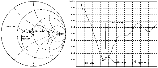
Figure 4 Figure
3
I made a new ground plane and center conductor for the antenna, put everything back together and soldered it. This corrected most of the problem. The resonance dip was still shifted to the right, though, but adjusting the length corrected this, and the new length agrees with numerical calculations. Figures 3 and 4 show the response of the new antenna. The worst case SWR (at 1100 MHz on Figure 3) is now about 1.48:1. This means that about 82% of the power goes out of the antenna and only about 18% is reflected back. On the Smith Chart (Figure 4), we can see that the antenna is more closely matched to the system as well.
If, after all of this, you find your marbles rolling downhill, don't worry. You don't have to understand all that to build a good antenna. Take a piece of copper-clad circuit board (single-sided, 1/16" thick, FR4 or G10 epoxy fiberglass-available from Radio Shack), cut it to the shape of the aluminum ground plane, and drill the center hole (3/8"). Get a piece of 1/4" bronze welding rod about 3-1/2" long and thread one end 1/4-28 about 3/4" to 1" down the rod. (Any brass, bronze or copper rod is fine; we just want something you can solder to and that's not possible with aluminum.) Assemble this as shown in Drawing No. 162, except leave off the lugs to connect to the coaxial cable.
The copper side of the circuit board should be 'up'. This puts it on the same side as the short end of the radiating rod-the back side of the antenna. Change the length of the rod from the 2.65" shown in the drawing to 3.10" (measure this with a dial caliper, not a ruler). Tighten the nuts-you can use Loctite if you wish, it won't affect the antenna.
To connect the antenna, strip about one inch of insulation from the coax and separate the braided outer conductor from the inner conductor. Strip about 1/4 inch of insulation from the inner conductor. Try not to nick either conductor during the stripping. Next, solder the braided outer conductor to the ground plane, close enough to the rod to allow yourself enough slack to solder the inner conductor to the rod, but don't let the braided part touch the nut or the center element.
Solder the center conductor of the coaxial cable to the exposed threads of the rod. You will need a heavier iron to solder to the rod because it's a pretty good heat sink-I used a resistance soldering iron which is like a pair of tweezers with current flowing through the tips. All the soldering is done on the backside of the antenna. You must be sure you have a good shiny solder connections here, otherwise the antenna will not perform well. I sprayed a conformal coating of silicone on the backside of the antenna to prevent corrosion, but depending on how it's installed in the plane, this may not be necessary. You should probably pot the end of the coaxial cable in epoxy to keep it from vibrating.
Electrically, the antenna is very good now. The transponder should be delighted with it, but ultimately someone will have to install it to be sure. My Falco has not reached that stage yet. The new antenna is also very sturdy, at least as sturdy as the old one. The two are also about the same weight. The one thing I did not measure was the radiation pattern of the antenna, I think Jim Wier did this though, and it should be okay. I didn't change the overall shape of the antenna so any 'nulls' or 'blind spots' in the old antenna will still be in this one. I think the problem was with the 'match' though, and that's fixed now.--Michael Scaturo
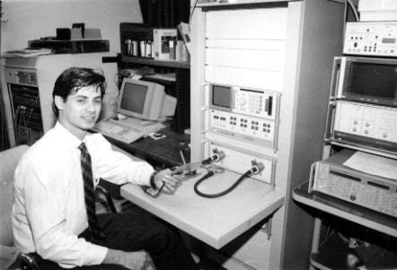
Michael Scaturo with the network analyzer and the antenna. This is
not the actual test because there is too much metal around the antenna.
More Notes
I also talked about this with the head of a local avionics shop. He said
that the transmitting operation of a transponder is a tricky business and
that the transmitting cavity, the cable and the antenna is a tuned device.
Any change in the impedance will affect the frequency, and anything tht
pulls the frequency off by more than 3 MHz will result in the Center not
seeing you. He said that seemingly insignificant things like a loop in
the cable, or running a cable near a landing gear motor can screw up the
works.
It seems obvious to me that the identification of the marginal electrical connection at high frequencies of the metal-to-metal contact is the primary problem and is what was screwing up the impedance. This is solved by changing materials and soldering the joints. Other than that, it's the same antenna we've been using.
Michael tuned the antenna to a transponder's transmitting frequency of 1090 MHz. By looking at the chart, he could see that the 2.65" length was too short. On the calculator, the length comes out to about 2.90" with an infinite ground plane, correcting for the finite ground plane brought it up to about 3.00". He then optimized the antenna on the Hewlett-Packard Network Analyzer by trial and error to work best with the transponder, and the length turned out to be 3.10" when he measured it at the end of the text.
Transponders receive at 1030 MHz, and I was worried if optimizing it to 1090 MHz would affect the reception. The avionics shop said to stop worrying about that, and that the transmitting was the critical thing. Fortunately, antennas are 'reciprocal', which means that antennas behave the same way when transmitting and receiving, thus any good transmitting antenna will also receive well.
Our DME antenna, which is identical to the transponder antenna, has worked wonderfully, but the improvements brought about by the change in materials and soldering will make for an even better antenna. The avionics shop said that DMEs use synthesizers, they're not load-sensitive and can tolerate a little SWR. DME frequencies range between 962 MHz to 1213 MHz, and the transponders 1090 MHz frequency falls in the middle of this band. You can see from the SWR plots that this band is better that it was before, so it appears to make sense to make the DME antenna exactly like the transponder.
I sent a copy of all this to Jim Wier for his comments. Jim said that he developed this antenna for Bellanca who sent him an entire wing, complete with all metal components, wiring, plywood covering and paint. He used the same methods and equipment that Michael Scaturo used, and Jim tuned the antenna for best reception in the Bellanca Viking wing. Nearby metal objects, carbon and aluminum particles in paint, and the like all have an effect on the antenna. The optimum length of the radiating rod will be different in free space than in a wing-and each wing is different.
Jim thinks that we must have some metal around our antenna that detuned the antenna. He didn't have this problem with the Bellanca Viking, and the plastic planes have not had the problem either.
As for making the antenna with soldered joints, Jim says, "I won't argue with that. I agree that it will make a better antenna. I used an aluminum ground plane and ring terminals because Bellanca vetoed the use of any soldering because it couldn't be assembled as quickly as the other method. Michael Scaturo did a professional job , and I applaud him for it."
Short of searching out loops in the coaxial cable and cables near motors, those of you with already-built Falcos have little opportunity to improve things without cutting into the wing. I was curious about those who, like Charles Gutzman, have put the antenna on the landing gear access panel-since you can't solder to aluminum, could you just solder to the rod and get an improvement? Michael said he first soldered the connection to the ground plane, and this gave him almost all of the improvement in the performance of the antenna. He thinks soldering to the ground plane is the really important thing.-Alfred Scott
![]()