Speed Gain From
Cowling Modification
![]()
Speed Gain From
|
|
by Cecil Rives
|
This article appeared in the December 1996 Falco Builders Letter |
The inspiration for this undertaking came from an observation of cooling air inlets on the cowling of a Glasair II that belongs to a friend of mine. His airplane shares the same roost with a Christian Eagle, a Glasair III, a Mini-Mustang and my Falco. (Sorry folks, but you have to take hangar space where you can find it!) The Glasair II uses the same 180 hp engine that is in my Falco, an IO-360-B1E, and also the same Hartzell prop. What caught my eye was the size of the cooling air inlets that are considerably smaller than mine. In fact, they measured about 38 square inches of total inlet area as compared to 75.5 square inches on N63KC.
When I commented to my friend on the small size he remarked that he had just made some inserts to make them even smaller-17 square inches total inlet area! These inserts are claimed to result in an 8-10 KIAS increase. As he had not installed them he was unable to verify the claim. With the 38 square inch inlets, the Glasair will climb at 85 KIAS and never exceed 350°F CHT nor 200°F oil temperature.
Well, all this and conversations with Alfred and John Harns encouraged me to see what could be done with my Falco. Some years ago, John Harns reduced the size of his IO-320 inlets and experienced a significant increase in speed.
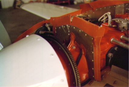
The baffle plate at the starter ring
I should preface what follows by pointing out that a year or so ago I had made every effort to seal all the nooks and crannies of the high pressure area of the engine compartment. Also, I made and installed a baffle plate on the front of the engine to seal off the starter ring area.
Alfred had suggested that I make some inserts or cuffs and experiment with different sizes to see which might give the best results. Using rigid foam, I roughed out a shape that would reduce the inlets by about three square inches per side, covered them with a mixture of epoxy and West's Microlite to smooth things out and secured them in place with duct tape. The test flight was encouraging as the CHT and the oil temperature all stayed "in the green", even though it was a 90 KIAS climb on a 35°C day.
At this point, I decided to reduce the inlets by an additional two and one-half square inches per side. All of this "filling in" was done on the upper lips of the upper cowling half and after this last reduction, little more can be added as you will be interfering with the attachment screws for the two cowling halves. The end result is an inlet opening of 32 square inches per side or 64 square inches total inlet area (measured one inch out from the spinner radius). This is still 26 square inches larger that the Glasair II.
For a climb test, I began at 2000' and leveled out at 8500'. I held 90 KIAS, maximum power, and full rich. Temperatures were stable throughout the last 400' of climb. At an OAT of 28°C, the CHT was 400°F and the oil temperature was 220°F.
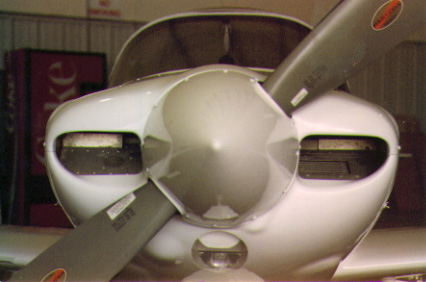
The photo above shows the cowling inlets after they were permanently installed and the cowling repainted (along with the rest of the airplane, but that's another story). I did a speed run at a pressure altitude of 4500' and 15°C OAT. The indicated airspeed was 172 knots, for a true airspeed of 187 knots, or 215 mph. This compares to a speed recorded on a flight a year earlier (at the same pressure altitude and OAT) of 166 knots indicated, or true airspeed of 180 knots or 207 mph. Thus, I've achieved an increase of 7 KIAS by a reduction of 11 square inches of cooling inlet area.
In the September issue of Sport Aviation there is an article by Jimmy Tubbs entitled "Engine Cooling Problems." The article describes a method whereby the pressure differential between the high and low pressure areas in the engine compartment can be determined in order to assess the cooling efficiency of the system. I assembled the apparatus described (a simple manometer). I installed it in the Falco and conducted a series of flight tests.

The manometer. The scale is graduaged in 1/2" increments.
In a climb from 2000' to 6500', I held a true airspeed of 85 knots, with full throttle, maximum rpm, and full rich mixture. At an OAT of 17°C, I recorded a CHT of 400°F and oil temperature of 210°F. The manometer reading was 6 1/2" and 3 1/2", for a 3" pressure drop.
For a cruise test, I flew the Falco at 5500'. With a power setting of 23'/2300, and leaned to 100° rich of peak, the plane indicated 150 knots. At an OAT of 20°C, the CHT was 325°F and the oil temperature was 210°F. The manometer reading was 6 3/4" and 1 3/4", for a 7" pressure drop.
Disconnecting the high pressure line of the manometer while in flight enables you to compare the low pressure area in the engine compartment with the static pressure in the cabin. This differential in N63KC is about 7 inches. [Because the cockpit pressure in a Falco is lower than the outside air-as can be witnessed by the blast of air you get from the back of the cockpit on a cold day-I think this reading is bogus.-Scoti]
As a result of all this, the following observations can be made.
1. Even though the CHT and oil temperature on my Falco are still in the green in an 85 KIAS climb, the 3" pressure drop indicates a less-than-desirable cooling condition as defined in the Tubbs article. (On a 28°C day it is doubtful that the CHT would stay in the green.)
2. At cruise, the CHT of 325°F is lower than Tubbs' recommended 370-390°F range. (John Schwaner in his book "Sky Ranch Engineering Manual" says that normal CHT range is 350° to 435°F.)
3. The oil temperature appears to be satisfactory in both climb and cruise as Schwaner states that a range of 160° to 245°F with 180° being a median value is desirable. Tubbs offers no value.
4. The 7" pressure drop from the high to low pressure area of the engine compartment indicates a damming up of the air in the lower part of the cowling according to Tubbs. Therefore, an increase in the exit area should increase the pressure drop with the upper part of the cowling and increase the cooling effect of the air flow. (It should be mentioned here that the total exit air area of the Glasair II is about 50 square inches compared to the Falco's 37 square inches.) [And Stelio Frati might mention that he did not design the Falco with a nose gear door to block the exit area!-Scoti]
In conclusion, it seems that we have a dilemma. We can increase the exit air area in order to improve climb cooling but that won't help the already too-cool cruise temperature. However, we could forget about the 85 KIAS climb (what's so sacred about it anyway?) and opt for a 100 KIAS climb. That gives you better visibility over the nose, too!
It does appear, though, that there is potential for a significant increase in speed over what I have experienced if one wants to add cowl flaps or take on the task of an extensive modification of the cowling. We're not even close to the air flow characteristics of the Glasair II. That airplane, by the way, lists a top speed of 228 mph. That's only 13 mph faster! And we're 40 years old! And, we're a lot prettier!
Incidentally, does anybody know of any hangar space in the Houston area? I'm getting a little weary of all the termite and woodpecker jokes.
Cecil Rives
|
September 16, 1998 |
Following a trip to the west coast Falco fly-in, Cecil sent us the sketch above. He said the cracks are surface cracks, apparently in the paint and possibly gel coat of the cowling only. Our suspicion is that the cowling mod described in the article above may have created additional stiffness in the cowling and caused loads to be concentrated in these areas and this may have created the cracking (which we have not seen in other Falcos).
By the way, on the trip, Cecil reported that he was getting a cruise of 190 knots (218 mph) true at something line 22/2300 at 6500 feet.
![]()