Making the Wheel Well Doors
![]()
Making the Wheel Well Doors |
|
by Al Dubiak
Here are a few pictures of the way we constructed the wheel well doors.
We made a belt out of 1/4" O-ring material and wrapped it around the tire and a small pulley driven by the electric drill. We used two-sided tape and attached 60-grit standpaper in strips over the outer surface of the tire.
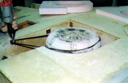
Then we cut a 2" thick foam board to the shape of the wheel well and stapled small stops on the sides of the wheel well so the foam board would only go down about 3/4". With the tire on the gear leg and retracted into the well, I marked the center of the tire location on the wing surface in both directions so that when the foam is inserted into the well without the tire, I could mark the center on the foam surface. We then cut out an 11" diameter section of the foam using the center marks from the tire reference markes.
We then put the tire back into the wheel well with one of the axle spacer washers and pressed the foam board down while rotating the tire. We continued this until the tire cleared away the foam. This gave us the same shape as the tire. We did this same process three more times adding another washer spacer each time to give the proper clearance between the tire and the gear door.
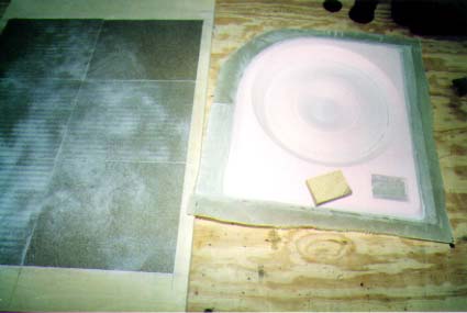
Then we removed the tire, positioned the foam back into the well and pushed it down to the stops on the side walls. Then we made a platform out of plywood to hold the 11" diameter piece about 3/4" below the inside surface. I then used a can of spray foam to secure the 11" piece.
Next I shaped the outside surface to match the wing and fuselage surfaces. After this, we applied the fiberglass cloth and epoxy to the outside surface. When this hardened, we then removed the door and placed the tire back into the well. Then we did the same process again, rotating the tire to make the inside 11" piece take the shape of the wheel and hubcap. Then we applied the cloth and epoxy to the inside surface.
|
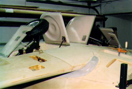
Please remember that when you use this method, the airplane is upside down and thus the landing gear legs have a tendency to rest in the wheel wells at a slightly 'higher' location than they will when right-side-up. In flight, the screwjacks will be under tension and this is not the case when the plane is upside down. Dr. Ing. Alfredo Scoti Al also mentioned that the note on the drawing said something about keeping the hinge straight. He found this a little confusing and said that the hinge should be 'flat'. What we're talking about here is to keep the pivoting line of the hinge in a straight line, even though the bottom of the airplane is curved. If the hinge is curved, it will not work. |
|
When I received the last FBL, I had just half-completed a pair of main gear doors which gave me no satisfaction at all. I was very interested to see the contribution by Al Dubiak. It looked good to me so I tried the method. It worked very well in all details, including the drive belt of O-ring material butt-joined with super glue-much to my surprise. I found that some contact cement on the back of the abrasive paper caused it to adhere to the double-sided sticky tape more firmly. My rather old electric drill could not take it and blew up-a heavy duty drill is required. I now have a respectable looking pair of main gear doors. I congratulate Al on a brilliant piece of lateral thinking. This may become the standard method of producing main gear doors. Ian Ferguson |
![]()