Flap Flutter
![]()
Flap Flutter |
|
|
From "Construction Notes" Falco Builders Letter, June 1993 |
In early April, the Falco G-MRCI developed a case of flutter in the left flap. At the time of the flight, the airplane was going through a flight test for the British CAA, since this Falco had been imported from the U.S., where it had been built by Charles Gutzman. The airplane was in a slight dive with the intention of taking the airplane to Vne, when at 205 mph indicated, the left flap developed a severe flutter. While the pilot immediately retarded the throttle, it was all over in a few seconds, and the flap departed the airplane. The pilot landed the airplane without incident, and reported that the Falco flew well with one flap missing.
The outboard flap hinge pulled off the bushing, leaving the bushing and aileron hinge bolt in place and unharmed (the inspector reported that none of the hinge bolts had washers under the bolt heads as called for in the plans). At the inboard end of the flap, the flap hinge remained with the airplane and also a short length of the flap spar.
In a preliminary report which we sent out to some of you, we reported that a substantial amount of free play existed in the actuator after the accident, however we have since learned that this is not correct. The large amount of free play in the system (after the incident) came from the movement of the actuator supports and center torque tube support. In the violent shaking of the flutter incident, these supports became loose because the wood was compressed under the supports and under the screw heads for the supports.
Flap flutter is an extremely rare event, however in consulting with engineers, flutter in flaps can happen if the conditions are right. Large flaps, like the Falco's, are more prone to flutter than flaps of small area. Free play should be reduced to a minimum, ideally less than 1/16" at the trailing edge, but in no case more than 1/8" at the trailing edge.
Charles Gutzman reported that this aircraft had previously had an incident of flutter in the left flap. This occurred in the first 10-15 hours of flight, and it happened on raising the flaps after takeoff. The buzz in the flaps was momentary and after landing, Charles Gutzman reported that he realized that the flap torque tube had been joined in the center with only one bolt (vs two bolts shown in the drawings). He subsequently installed the second bolt and "tightened the system up". Charles Gutzman reported that after this, the system had very little free play.
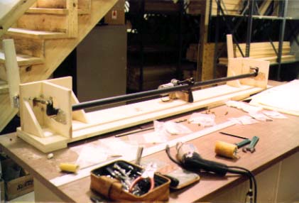
Flap control test rig.
Our analysis of this incident has brought us to the conclusion that this incident was caused by six factors:
1. Free play in the flap control system. If you take the trailing edge of the flap in your fingers and jiggle it, there is a certain unavoidable amount of 'jiggling free play' which results from the sizes of the bolts within the bushing and bearing holes. Some of this can be reduced by tightening the bolts on each end of the flap actuating pushrods, however to reduce this 'jiggling free play' requires replacing the existing bolts with close tolerance bolts. The use of close tolerance bolts will reduce the jiggling free play to 1/16" or less at the trailing edge.
2. Flexing in the flap control system. If you push hard on the trailing edge of the flap, you can observe that, in addition to the 'jiggling free play', the flap control system also has a certain amount of flexing in it. In our analysis of this, we observe that the center flap torque tube support (P/N 726) moves slightly relative to the flap actuator support brackets (P/N 854-1 & -2). The rigidity of this part of the system depends partly on the rigidity of the three metal components, and also on the rigidity of the mounting on the spruce block in the bottom of the fuselage.
3. Use of countersunk screws. The flap torque tube support (P/N 726) and the flap actuator support brackets (P/N 854-1 & -2) are installed with washer-head screws with the head of the screws on the outside of the plywood skin of the aircraft. On this Falco, the screws were countersunk into the surface with the result that the heads of the screws bear on spruce. This weakens the mounting and adds to the flexing in the flap control system.
4. Out-of-balance condition. Ordinarily, flaps for production aircraft are not balanced. This is true for both the SF.260 and the Falco, which have very similar flap control systems. However, we have found that there is a very wide variation among our builders on the trailing-edge weight of the flaps. A heavy weight at the trailing edge would increase the tendency of the flaps to flutter. It is evident that we must impose an upper limit on the flap trailing-edge weight.
5. Reflexing of the flaps. The flaps of this Falco were reflexed five degrees. This was in an attempt to increase the speed of the airplane, but Charles Gutzman reported that it did not increase the speed at all. While reflexing of the flaps is not something which would cause flutter by itself, when the other conditions are existing, we believe the reflexing contributed to the conditions which caused the flutter incident. To explain, with the flaps in the normal 'trail' position, the air loads would cause a constant 'up' load on the flaps, pushing the flap control system to the limit of the 'jiggling free play' and against the flexing in the system. If the flaps are raised beyond the trail position, at some point they would enter a neutral zone in which the flaps would be neither pushed from below or above, but rather simply buffeted by turbulence. We think this reflexing caused the conditions of buffeting which induced the flutter incident.
6. Omission of washers under hinge bolt heads and nuts. The inspector reported that no washers were installed under the hinge bolt heads or under the nuts for any of the control surface hinge bolts. The outboard flap hinge pulled off its bushing and was not restrainted from doing so by a washer under the bolt head. It is impossible to know, however, if the outcome would have been any different if the washer had been in place.
The Falco has been built with three types of control surfaces. The original Series I and II Falcos, had wood-and-fabric control surfaces with open bays aft of the spars. These were covered with fabric. The Series III and IV Falcos had aluminum control surfaces. Many of our early Falcos were built with the original wood-and-fabric method, but most have been made by covering them entirely with plywood-as was the Falco G-MRCI.
We asked that builders weigh the flaps, by removing the flap pushrod, suspending the flap on its hinges (on the airplane or on a bench), and with the flap in the horizontal (flight) poition, to measure the weight of the trailing edge of the flap at a point 5mm outboard and 5mm forward of the innermost trailing edge point of the flap. The overall weight of the flap is not something we want to know.
Four Falcos with wood-and-fabric controls were weighed this way. The weights were: Karl Hansen 14, Neville Langrick 20, Larry Black 20 and John Oliver 19.5/20.4. (All of the weights are in ounces, and double weights are for left and right flaps.) Gar Williams measured the trailing-edge weight of his Series III production Falco at 21 oz.
For the Falcos with plywood-skinned controls, there was considerable variation. Here are the numbers: Cecil Rives 29 (in primer, not painted yet), Jonas Dovydenas 32, Dick Reichenbach 19.8/20.3, Rex Hume 20, John Shipler 27/27.8, Ray Purkiser 20/21, Guido Zuccoli 27/30, Steve Wilkinson 27, Bob Bready 23/24, and G-MRCI 37.4 (for right flap).
Note the substantial variation from one airplane to another, and also that when both flaps have been weighed for an airplane, with one exception, the weights have come within one ounce of each other. Thus we think it is logical to conclude that the unrecovered left flap of G-MRCI was within one ounce of the 37.4 oz weight of the right flap. As you can see, it is quite heavy.
While the Falco has been flying for 38 years, it's all too easy to dismiss this type of incident as the mistake of another builder. This could happen again if the conditions are right, and we all ought to reflect that this could easily have been a fatal accident.
After analyzing this problem, we have determined that there are a number of sensible steps that we can take to prevent this from happening again. The details of these are included in our Service Bulletin No. 93-1 (which is essentially a word-for-word copy of what is here, along with some instructions for how to accomplish the corrective actions on finished aircraft) and our latest revisions.
The corrective measure are: balancing the flaps, using close tolerance bolts in the flap control system, and installing reinforcing straps between the center torque tube support and the flap actuator support mounts.
The flutter experts say that the most desirable and easiest way to solve this problem is to eliminate the free play in the system, and so that we could fully understand all of this, I put together a flap control system on a bench. This is shown in a photo on page 11, and the components are mounted on 3/4" baltic birch plywood, which is very rigid and strong. With this setup, we were able to push and shove on the system and to locate the free play.
The close tolerance bolts are used to eliminate as much free play as possible. Ideally, we would like to see the free play down to about 1/16" at the trailing edge. Some of our Falcos with the existing hardware have this little, while others have 1/8" or more. On our mockup, the free play went from about 1/8" to 1/16" when the close tolerance bolts were installed.
In addition, you can eliminate some free play by tightening up the bolts snugly against the spherical bearings at each end of the flap pushrod. Because of the slight gap between the slot in the end of the flap pushrod and the bearing in the flap hinge and arm, some builders have put a shim washer in there. You would be amazed at how much difference it makes to tighten up around these bearings.
It was apparent to everyone that there is a certain amount of flexing going on at the center of the aircraft, and this is very difficult to see or measure on finished aircraft because of the close quarters involved. On the test rig, however, it's quite easy to see and measure. If you press down hard on the flap, you can measure about .030" of flexing between the two supports-which translates to about 3/16" movement at the trailing edge. That's when mounted on solid birch plywood; when mounted on spruce, it would certainly flex more.
I was feeling rather sheepish about this, because we designed the actuator mounts, however in watching the movement of the parts in finished aircraft, it's apparent that the original Frati-designed center mount is moving slightly more than our parts. That's certainly because of the use of two mounting screws instead of four, and because of the greater base area of the brackets on the spruce.
On G-MRCI, however, these supports were mounted in the airplane with the screws countersunk into the wood. This makes them bear on spruce, and it is nowhere near as strong.
Let's also look at the bright side of things. We now know that in a case of destructive flutter that causes a flap to break off and depart the airplane, that the flap actuator and other components are sufficiently strong to withstand the forces, but that the center torque tube support and actuator supports will compress the wood under them and become loose. (Those of you who have been for the Big Slide, can expect some looseness in these parts.)
The flexing can be eliminated by installing braces between the supports. I've already done this on the mockup, and it makes a remarkable difference. Once these components are tied together, then the loads that go into the bottom of the fuselage are just the torsion loads from actuator.
We are in the process now of collecting all the necessary parts, and we will be sending them out to those of you who have bought the various kits. The installation of the braces will be a difficult job for those of you with finished or nearly finished airplanes, however it will be quite easy for the rest of you.
Eliminating the free play and the flexing is very important, but it is also obvious that we must establish some sort of balancing limit on the flaps because flaps with heavy trailing edges gets you off into the area of the unknown. In establishing these limits, we're simply requiring that all of you build the flaps with the same sort of balance that has existed in the Falco for 38 years. We're looking for 20-21 oz. at the trailing edge, with an upper limit of 23 oz., however anything under 20 oz. is fine.
Finally, we'd like to see an end to this business of reflexing the flaps. If you get the system balanced, eliminate the free play and the flexing, then reflexing probably doesn't make any difference. But look at it this way: Since reflexing doesn't give you any extra speed and since it is identified as a possible contributing factor to flap flutter, why do it at all?
I'm sure many of you will be tempted to take halfway measures here, or to call me to ask if you really have to do it all. The answer is that we can identify four conditions which probably caused the flap flutter and two more conditions which contributed to it. Does that mean that you'll never have flap flutter if you eliminate one, two or three of these conditions? We don't have the slightest idea and, more importantly, we don't have any idea of how 'close to the edge' you will be walking. This incident could have been a fatal accident, therefore it only makes sense to us to eliminate all of the conditions which probably caused the flutter.
Alfred Scott
|
From "Construction Notes" Falco Builders Letter, September 1993 |
At this time, many of you have installed the reinforcement for the flap actuator. Everyone who has done it reports an astonishing improvement in the stiffness of the system. Getting to the actuator is a problem with finished aircraft, but some builders have reached the actuator by simply cutting out the vertical walls of the wheel well, that is, the section aft of frame 5. After the repair is made, they just glued in a new plywood wall.
I also want to remind everyone on the importance of using washerhead screws which bear on the plywood skin of the fuselage. This is dramatically stronger that countersinking screws into the spruce, and I've only recently learned that in the case of Falco G-MRCI the screws had actually pulled loose prior to the flap flutter incident. A couple of weeks before the incident, the owner and a friend were taxiing out for takeoff. They lowered the flaps but then noticed that the flaps had not lowered at all. They taxied back, inspected the system and found that the screws had pulled loose from the wood. Instead of the flaps lowering, the actuator had climbed up the actuator screw. The owner replaced the screws and also installed a stiffening aluminum plate.
On many airplanes, the flap system has an up-stop such that when the flaps are completely raised, they lock into position by bumping into a solid part of the airframe. Larry Black pointed out that this is possible on the Falco as well, and he's got a good idea. Many of you, in an effort to reduce the drag of the airplane, seal the gap at the inboard end of the flap. There are two ways of doing this. One is to screw a piece of aluminum sheet metal to the bottom of the flap so that it overlaps the gap and hits the bottom of the wing.
A similar method is to build a little spruce lip/extension on the inboard end of the flap and then glue a similar and matching strip of spruce on the wing so that when the flap comes up, these two pieces of spruce hit and seal the gap. There's certainly nothing wrong with this type of sealing, and Larry points out that this sort of overlapping integral seal will also serve as an up-stop on the flaps so that when the flaps are fully raised, the spruce seals contact each other and give additional rigidity to the flaps.
|
From "Construction Notes" Falco Builders Letter, December 1993 |
After the flap flutter incident reported in our last FBL, Matt Clark got his Falco back in the air with all of the modifications done in October. After flying G-MRCI for 1.5 hours, he had another incident of flap flutter. Matt was flying the airplane at 2,000' in perfectly smooth air and indicating 150 mph when the right flap fluttered and disintegrated. Matt said the airplane experienced moderate to severe vibration for about two seconds.
The flap hinge at the outboard end was sheared off, and the flap broke in two, roughly mid-span for the flap. The inboard end of the flap stayed with the airplane, trailing at 45° down and aft. He landed the airplane without further incident.
Matt Clark reports that all modifications had been installed and that the system was very rigid, and the flaps were no longer reflexed. However, he said that in the process of balancing the right flap, they had to add a substantial amount of weight to the leading edge with the result that the right flap was roughly twice as heavy as the newly built left flap.
After the incident, the remaining part of the flap was shipped to Francis Donaldson, chief engineer with the Popular Flying Association, which is similar to the EAA but which also licenses homebuilt aircraft. Donaldson reported:
1. There is roughly 1mm thick filler all over the outside surface beneath the paint at the point which is now exposed in cross-section.
2. The flap leading edge was covered with two layers of 1mm plywood instead of the single layer of 2mm plywood shown in the drawings. At the point where the flap broke, the inner layer of plywood was feathered off as if meant to be spliced at this point, but the glue on the feathered area had obviously never been in contact with the matching part. Also, the two plywood skins were not glued tightly together; there was a void between them. The net result, he thinks, is that there must have been a weakness in the plywood skin which encouraged failure at this point.
3. At the break, the 15x15 leading edge spruce strip had been drilled through and a slug of lead glued into the hole. The effect of this was that the leading edge member was effectively cut through at this point-another weak point that would encourage a failure at that point.
4. There were no drain holes in the flap, and the vent holes drilled in the ribs were blocked with varnish. He pointed out that this raises the possibility that the skins may have opened up in flight or that there might have been water in the flap, however there was no sign of either problem.
In mulling this over, Donaldson and I have reached similar conclusions. The two flutter incidents are probably the same mode of failure. They come within two flying hours of each other, and the logical remedies of stiffening up the system, eliminating the free play and balancing the flaps obviously did not help this aircraft. We can see that this latest flutter incident occurred at a substantially lower speed (150 vs 208 mph indicated), and we also know that because of the balancing this flap was substantially heavier than it was before.
The distance between the flap hinge supports is substantially greater than for any other control on the Falco. As anyone familar with musical instruments knows, increasing the length of a guitar string lowers the note, and the heavier the string the lower the note. The same is true of any control surface on an airplane, and it's apparent this flap failed in bending. We know that the flap which fluttered in April was exceptionally heavy due to the amount of filler used on the airplane, and the addition of the balancing weights to the right flap made it even heavier still.
Donaldson and I both think that a heavy overall weight of the flap, regardless of any balancing, can bring it into an area where it at risk of flutter, and that the addition of balancing weight to the leading edge may be counter-productive in that it could lower the resonant frequency of the flap. Francis Donaldson says, "I had come to a similar conclusion that the relatively long span between the hinges on the flap might be causing a problem with the flaps failing in a flutter mode essentially in bending, and that by adding significant weight to the flap in the middle this may lower the bending-mode frequency and lower the flutter speed."
Francis Donaldson and I had quite different views on the role of the filler material used on the control surfaces. Donaldson said, "I find it hard to believe that a layer of filler this thick could add as much weight to the flap as this one seems to have done." I found it easy to believe.
The Falco has been turned over to Andrew Brinkley, England's premier Falco specialist, for repairs. On receipt of the control surfaces, Andrew found all of them out of balance to an astonishing degree. At station 11, the ailerons weighed 40.5 oz. (right) and 35 oz. (left) vs a balancing spec of 18.5±2 oz. The rudder weighed 45 oz. at station 2 (without nav/strobe light which adds 5 oz.), vs a balancing spec of 24±3 oz. The elevator weighed 74.5 oz. vs a balancing spec of 39±6 oz. The right aileron and rudder contained electric trim motors (Mac trim systems).
I asked Charles Gutzman, who built the Falco, about this. Charles said he balanced the control surfaces before painting, but not after painting. "I couldn't imagine that paint would make that much difference, but apparently it did."
(As it happened, George Barrett called the other day and reported some numbers on his Falco. This ailerons balanced to 16/16.5 oz. before fiberglass/painting and ended up at 20.5 oz. each. Similar weights for the rudder were 24 oz. before and 35 oz. after.)
The fundamental lesson that we can take from these two flap flutter incidents is this: if you make the flaps heavy, they can flutter in a bending mode, even if balanced. It would be wonderful if we could know with some precision what the 'break point' weight is, but we don't and probably will never know this. We know that flaps built with a normal amount of paint have a 38-year history of trouble-free operation.
Second, if you must add weight to balance the flap, it would be best to add the weight near the ends of the flap where it will not lower the bending-mode frequency. Flutter specialists generally want a balancing weight evenly distributed along the leading edge, but this clearly is a different situation.
Third, drilling a series of holes in the leading edge strip is probably the wrong way to add weight because it creates a weak point in the structure.
Finally, be aware that the rigidity of the flap in bending comes not only from the spar but also from the plywood skin. A poor scarf joint will create a weak point in the flap, make it much less rigid and more susceptible to an incident of flutter.
Thus, it appears that we have discovered a new way to screw up in a Falco, and we all now have another reason to build a light aircraft. Dave Thurston and Stelio Frati each have over 50 years of experience in aircraft design, and both engineers say they have never heard of a case of flap flutter before. Yet in this airplane, we have seen two flap flutter incidents within two flying hours. It is very clear that these conditions can be duplicated in any Falco with identical results.
I've noticed that there is a considerable difference in weight from one builder to another on the control surfaces. With the all-plywood skinning method, some builders curse us because we should have told them that they were going to need to add three pounds to the leading edge, while others say that they didn't have to add any weight. I think very few Falco builders are aware of how much weight they can add to the control surfaces by generous applications of varnishes to the inside or fillers and paints to the outside. Primer/surfacers like Awlgrip are mixtures of industrial talc and epoxy, and they are very heavy.
George Barrett found that his ailerons and flaps added only about 4 oz. to the trailing edge balance point when he added the fiberglass cloth, epoxy and paint, however on the rudder the trailing-edge weight went from 24 oz to 35 oz. George says he cannot account for the large increase in weight to the rudder. The weight penalty for trailing edge weight can be surprisingly large. In this case, George had to add 40 oz. in balancing weights to offset the 10-11 oz. overweight.
To do this, George made three lead balance weights. Two of these were flat weights that are glued and screwed to the leading edge rudder ribs at the upper hinge opening. These weights were shaped like the leading edge ribs-indeed, he just used the finished rudder to form the casting sand-but the weights are tapered so that they are thicker in the front. These weights, which weighed 8 oz. each, were installed with screws and 3M epoxy left over from the cowling kit.
George also made an internal weight for the lower leading edge section of the rudder. He cut a hole in the rib so he could reach in to the area above the diagonal rib, then made a wooden mold of the inside of the rudder. The casting sand would not retain the shape required to make a groove for the leading edge strip, so George put a 9x9 stick in the mold before pouring the lead. This lower weight was 24 oz. and George installed it with 3M epoxy and four AN525-10 washerhead screws and nuts.
![]()