Simo on Falco
![]()
Simo on Falco |
|
by Dennis Simo
|
This appeared in the March 1990 issue of the Falco Builders Letter. |
While waiting for our delivery of Aerolite, we practiced with pine and carpenter's glue to determine the best way of jigging the ribs. We arrived at a simple solution that is fairly quick and very accurate using combined methods from past builder's letters and previous experience. We attached the blueprints to 1/2" particle board and covered them with clear mylar or acetate sheets. Nail on positioning blocks as usual, except for the outside of the bottom capstrip.
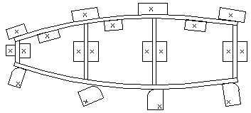
Here you make rectangular blocks with one corner radiused off and nailed near the bottom in such a way that you can rotate the block away from the capstrip after you've finished trial-fitting everything. By using the capstrip cams, gluing-up need not be such a messy, oh-my-god kind of procedure, especially when fast glues like Aerolite are used. It also makes removing the finished ribs easier and the jigs reusable.
The only downside to this method is the damage done to the blueprints and occasionally covering up some tid-bit of information. Although we made all of the ribs double-thickness and sliced them in half to save time, I would not recommend making wood parts to anyone who doesn't like doing this sort of meticulous work. Sequoia's rib kits are a bargain at twice the price.
A note on bandsawing: buy a new 1/2" blade with 6 to 8 teeth per inch and then-with the saw running-very carefully touch the sides only with a sharpening stone to remove the set or stagger in the teeth. This will make it difficult to cut curves but to split ribs in half, it will leave a much smoother finish, eliminating about 80% of the sanding.
The spars were not as straightforward since none of the drawings were full scale, but we transferred the dimensions by essentially redrawing the spars on particle board and covering with mylar those areas that would come in contact with the glue. Clear packing tape works well also.
The lazy man's solution for the forward fin spar was to have the blueprint enlarged by someone with a stat camera. Carefully check for any discrepancies and then trace onto drafting mylar to "thin" the lines down. Think of this spar in three groups of subassemblies: the "ladder" which consists of the two long uprights and all the rungs in between; the "hoop" being the laminated fuselage former, and the "ears" being the solid pieces of spruce in between. Cut the mylar ladder and ears and all the remaining airspace out from within the hoop and using what remains as a template which you will use to trace and cut a plug from 3/4" particle board. Shoot the ends of the hooplines across each and mark the intersection. Bore two holes kitty-corner to the hoopline intersection, and you should end up with a thing that looks like those coin-op binoculars at Niagara Falls.
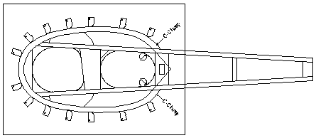
Screw this plug to another larger board with a sheet of mylar between. By using C-clamps in the holes, you can wrap soaked strips around, let them dry and then mount capstrip cams so you can glue up the strips around the plug. Put the cams on so you tighten the strips inward and upward. Cut the ladder portion off of the remaining mylar and use it to make the ladder as done for the ribs. Glue the remaining bits and pieces onto spruce stock and cut, sand and fit the ears.
When the hoop is glued up, sand off the uneven edges. Glue ears to ladder, and then align on the hoop to mark where the offshoots need to be cut off. The two subassemblies should fit together perfectly. Remove the plug from the hoop jig and glue the two subassemblies together. Quick and painless.
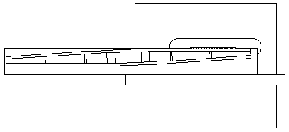
The rest of the spars were relatively easy with the tapering being easier than first feared. It was our sliding-bed panel saw that made our day, but just as simple a setup can be had on a regular table saw. Rip a 12" by 8' piece of 1/2" particle board, align the taper lines on the glued-up spar with the edge so that what you don't want is hanging off and attach spar to board using long screws and big washers through the center and hot-glue "welds" around the outside. [Excuse me for interrupting, Dennis, but I can't recommend high-viscosity cyanoacrylate glues with accelerators-Zap-A-Gap and Zip-Kicker-too highly for this sort of thing. In a couple of minutes you can glue blocks around the spar and knock them off when you're finished.-Alfred Scott] Now run the board through the saw again at the old setting.
For the tapers on the forward faces of the stabilizer spar and fin spar, we used a carriage-rails-and-router setup with a custom 1/4"Ø planer-bottom bit.
Scarfing the plywood for the aft face of the spar was also done on the table saw with a right-angle beam clamped to the sliding bed and the blade offset to 4 degrees (about a 15:1 slope). 3M rubber cement tape was used near the bottom and staples near the top to hold the plywood tight against the L-beam.
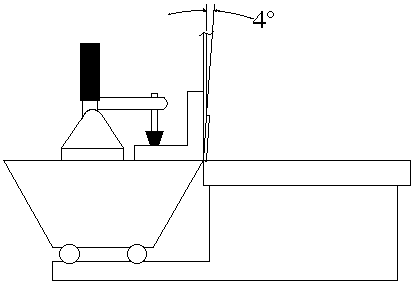
A similar setup can be achieved on a regular table saw by cutting a block to 8 degrees and then setting the blade to 4 degrees, attaching the plywood in the same way, but watch your fingers.
To date, our only mistake was a bad glue line on the plywood face of the main stabilizer spar. The problem compounded itself since all of our spruce was cut very close to the finished size to maximize the yield. When we milled off the offending plywood and enough spruce to clear the glue penetration, there remained less than the specified thickness overall. We hope to correct this problem by adding a 2mm-skin on the forward side between stations #2. All other experiences with Aerolite have been more than satisfactory.
|
|
![]()